The pressure transmitter working principle is based on converting mechanical pressure into an electrical signal that a PLC, controller or monitoring system can understand. Process pressure first acts on a sensing element such as a diaphragm. The resulting deformation changes an electrical property—commonly resistance or capacitance—and electronics then condition this change into a standardized output such as 4–20 mA, 0–10 V or a digital signal.
This conversion allows a pressure transmitter to continuously report actual system pressure rather than simply indicate whether a preset limit has been reached. It is widely used in water systems, compressors, HVAC, hydraulic equipment and industrial automation.
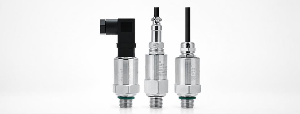
The pressure transmitter working principle converts pressure-induced mechanical deformation into a proportional electrical output for continuous measurement and control. Pressure is force acting over an area. In SI units, 1 Pa equals 1 N/m², as defined in the NIST pressure unit guidance.
Inside the transmitter, the process medium applies pressure to a diaphragm or sensing element. As pressure changes, the diaphragm deflects by a very small amount. This movement changes the resistance, capacitance or electrical characteristics of the sensor.
Signal-conditioning electronics then amplify, compensate and linearize the raw signal before converting it into the required output.
A typical sequence is therefore:
Process pressure → diaphragm deformation → sensor response → signal conditioning → standardized output → PLC/BMS/controller
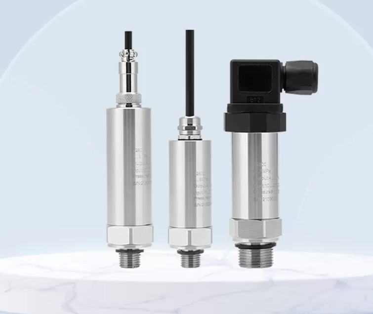
ANWOLL's pressure transmitter range illustrates this principle with ceramic and oil-filled silicon sensing designs for industrial pressure measurement. Its product family supports outputs including 4–20 mA and voltage signals.
Different pressure transmitter technologies use different sensing elements, but all convert pressure-related deformation into an electrical quantity that can be measured and transmitted.
| Sensing Technology | Basic Principle | Typical Advantage |
|---|---|---|
| Strain gauge | Pressure changes electrical resistance | Wide industrial use |
| Piezoresistive silicon | Silicon resistance changes under strain | High sensitivity |
| Capacitive | Diaphragm movement changes capacitance | Good low-pressure performance |
| Ceramic diaphragm | Pressure deforms a ceramic sensing element | Corrosion and wear resistance |
A strain gauge pressure transmitter typically uses resistive elements arranged so that diaphragm deformation produces a measurable resistance change. Piezoresistive silicon sensors work on a similar principle but use semiconductor material for higher sensitivity.
A diaphragm pressure transmitter can use a ceramic element where pressure deformation is converted electronically. ANWOLL's PT12, for example, specifies pressure ranges extending up to 60 MPa, depending on configuration, with 4–20 mA and several voltage-output options.
Regardless of sensing technology, accuracy depends on more than the sensing element. Linearity, hysteresis, temperature effects, repeatability and long-term drift all contribute to overall measurement performance. The international IEC 62828-2 standard for pressure transmitters defines specific testing procedures for industrial pressure measurement transmitters.
In a 4–20 mA transmitter, the measured pressure range is converted proportionally into a current between 4 mA at the lower range value and 20 mA at the upper range value.
The usable span is 16 mA. For a linear transmitter:
Output current = 4 mA + 16 mA × percentage of pressure span
For example, consider a transmitter calibrated from 0 to 10 bar. At 0 bar, its output is 4 mA. At 10 bar, it reaches 20 mA. At 5 bar, or 50% of span, the expected output is:
4 + (16 × 0.5) = 12 mA
At 6 bar, the output is approximately 13.6 mA.
The 4 mA lower value is useful because it provides a “live zero.” A healthy transmitter at zero process pressure can still produce 4 mA, helping the control system distinguish normal zero measurement from some wiring or power faults.
The HART communication protocol can also carry digital information over the same 4–20 mA loop while preserving the analog process value. FieldComm Group reports that more than 40 million HART-enabled field instruments are deployed worldwide.
ANWOLL's oil pressure transmitter provides a practical example: PT13 supports 4–20 mA, 0.5–4.5 V, 0–5 V, 0–10 V and RS485 configurations, with pressure ranges extending from vacuum/low pressure up to 60 MPa depending on the model.
The primary pressure transmitter function is to provide continuous, proportional pressure information for monitoring, automation and closed-loop control.
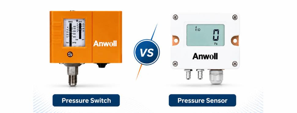
Unlike a pressure switch, which normally changes state only when a threshold is reached, a transmitter continuously tells the controller how much pressure exists.
Typical applications include pump and compressor monitoring, hydraulic systems, refrigeration equipment, water supply, pneumatic machinery and process automation.
When selecting a transmitter, engineers should consider:
Pressure type and range: gauge, absolute or differential pressure and the required measurement span.
Accuracy: select according to the actual process requirement rather than automatically specifying the tightest tolerance.
Output signal: 4–20 mA is widely used for industrial transmission, while voltage or digital outputs may suit compact controllers.
Process medium: wetted materials must be compatible with the gas or liquid.
Temperature and environment: verify operating temperature and enclosure protection.
Overpressure capability: pressure spikes should remain within the manufacturer's limits.
The pressure transmitter working principle is simple in concept, but correct product selection depends on matching the sensor, range, output and materials to the actual system.
ANWOLL applies several sensing technologies across its pressure measurement products, allowing the measurement principle to be selected according to medium, range and control requirements rather than using one transmitter design for every application.
The pressure transmitter working principle consists of four essential stages: pressure acts on a sensing element, the element deforms, electronics convert that deformation into a measurable signal, and the transmitter sends a standardized output to the control system.
Whether using ceramic, silicon, capacitive or strain-based sensing, the core pressure transmitter function remains continuous pressure measurement. Understanding how sensing technology and 4–20 mA conversion work makes it easier to specify the right transmitter for industrial automation, HVAC, water and machinery applications.
Pressure deforms a sensing element, and that mechanical change is converted into a proportional electrical signal.
The 4–20 mA loop provides a standardized industrial signal with a 4 mA live zero and a 16 mA measurement span.
For a linear transmitter, 12 mA represents approximately 50% of the calibrated pressure range.
A sensor produces the basic pressure-dependent signal; a transmitter conditions that signal into a standardized output suitable for control systems.
Common technologies include strain-gauge, piezoresistive silicon, capacitive and ceramic diaphragm sensing.
Match pressure range, accuracy, output, medium compatibility, temperature, process connection and overpressure capability to the application.